
5 Common Causes and Solutions for Large Temperature Control Fluctuations
Key Summary
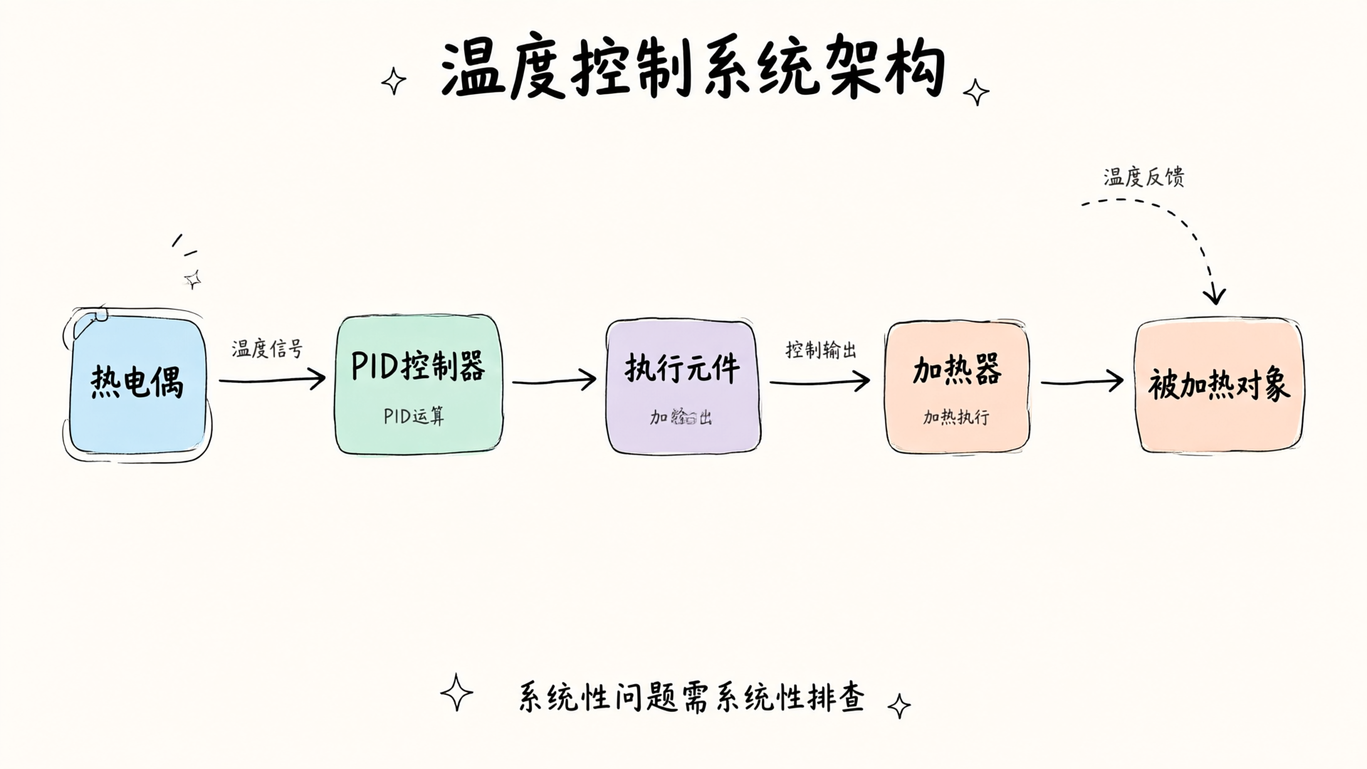
Drawing on experience serving over 500 industrial clients, we've identified the 5 most common causes of temperature fluctuations—including thermocouple selection, PID parameter optimization, heater maintenance, environmental interference, and control system delays—along with their solutions.
Key Points
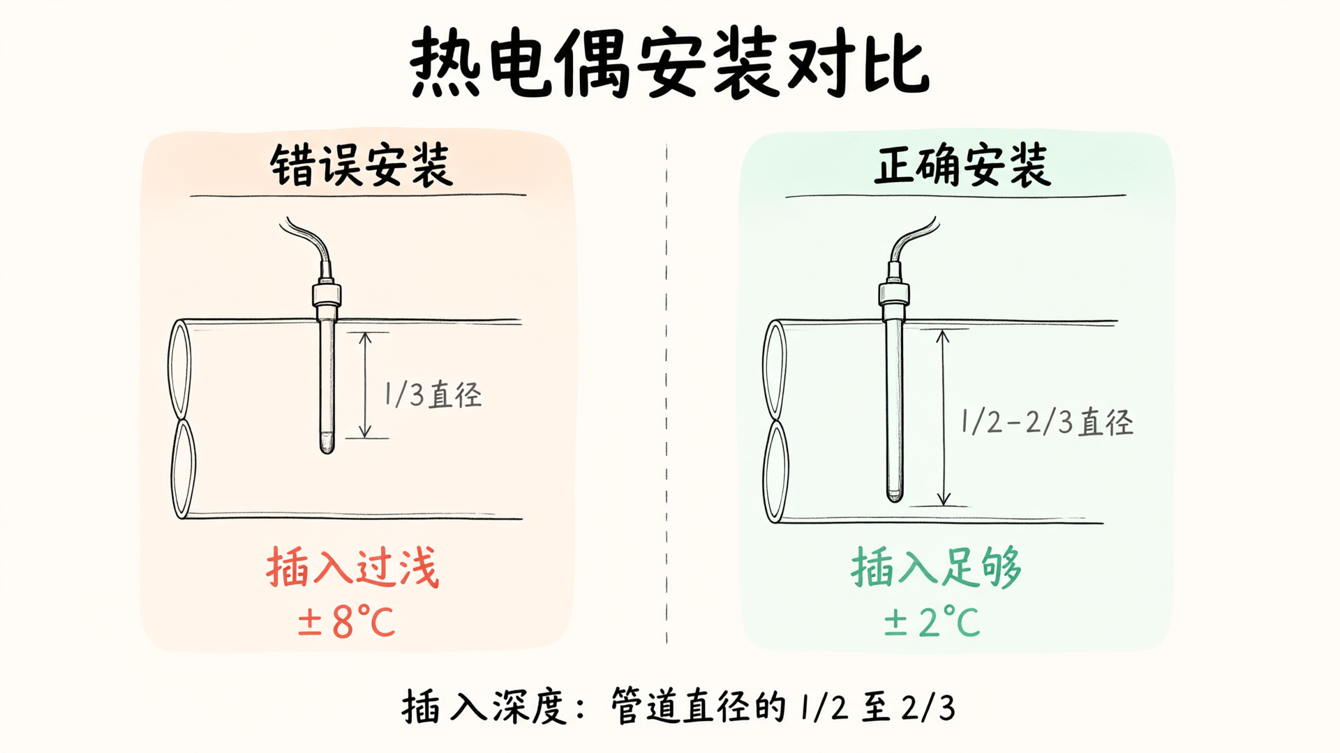
- 1Thermocouple selection and installation quality directly determine measurement accuracy. Insertion depth should be 1/2 to 2/3 of the pipe diameter.
- 2Up to 40% of temperature fluctuations stem from PID parameters not being optimized for actual operating conditions.
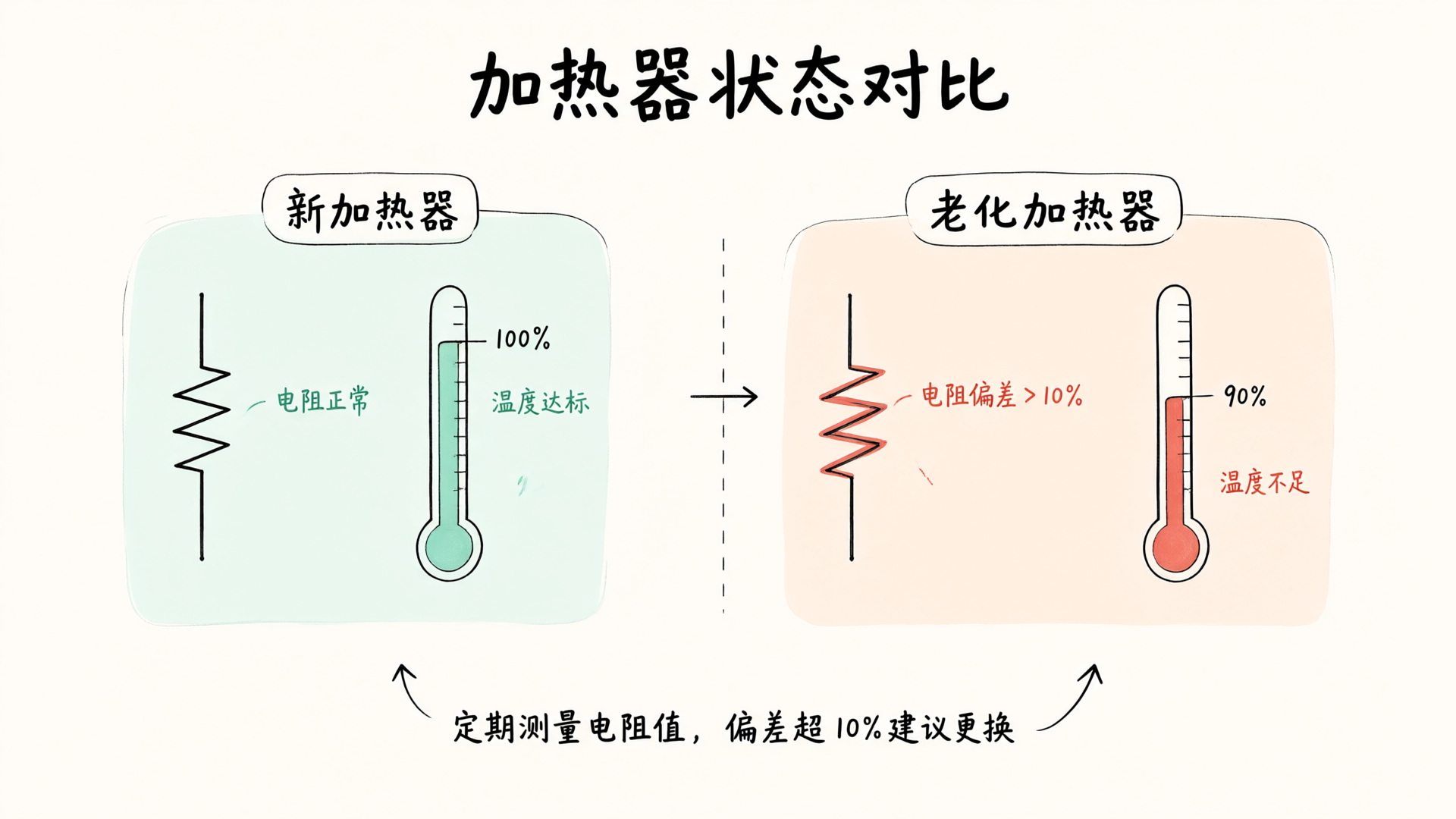
- 3Replace the heater if resistance deviation exceeds 10% after prolonged use.
- 4Thermocouple signal lines should use shielded cables, maintaining a separation of at least 30 cm from power cables.
- 5Control cycle settings follow the principle of short cycles (1-3 seconds) for heating and long cycles (5-10 seconds) for holding.
In industrial heating processes, temperature control precision directly impacts product quality and production efficiency. When actual temperatures deviate beyond the allowable range from the setpoint, yield drops, energy consumption rises, and entire batches may be scrapped. Temperature fluctuations are rarely caused by a single fault; they often stem from multiple system issues. Drawing on our experience serving over 500 industrial clients, we've outlined the 5 most common causes of temperature instability and their corresponding solutions.
Improper thermocouple selection or installation
Thermocouples are the core sensors for temperature feedback; their selection and installation quality directly determine measurement accuracy. K-type thermocouples are suitable for a range of -200°C to +1372°C, J-type is ideal for reducing atmospheres, and T-type offers superior stability at low temperatures. Incorrect selection leads to measurement errors, typically manifested as a persistent deviation between the setpoint and actual value.
Installation location is equally critical. The thermocouple's measuring tip should be positioned as close as possible to the heated object while maintaining an appropriate distance from the heat source. Insufficient insertion depth causes measurement lag, and improper angles make readings susceptible to airflow interference. In one case at an electronics manufacturing facility, reflow oven temperature fluctuated by ±8℃. Investigation revealed the thermocouple was inserted too shallowly—only 1/3 of the pipe diameter. After adjusting the depth to 1/2 of the pipe diameter, fluctuations were reduced to within ±2℃.
Solution: Select the appropriate thermocouple type based on the operating temperature range and atmospheric conditions. Ensure insertion depth is between 1/2 to 2/3 of the pipe diameter. Regularly inspect the thermocouple for signs of oxidation, discoloration, or damaged insulation, and replace it immediately if any issues are found.
PID parameters not optimized
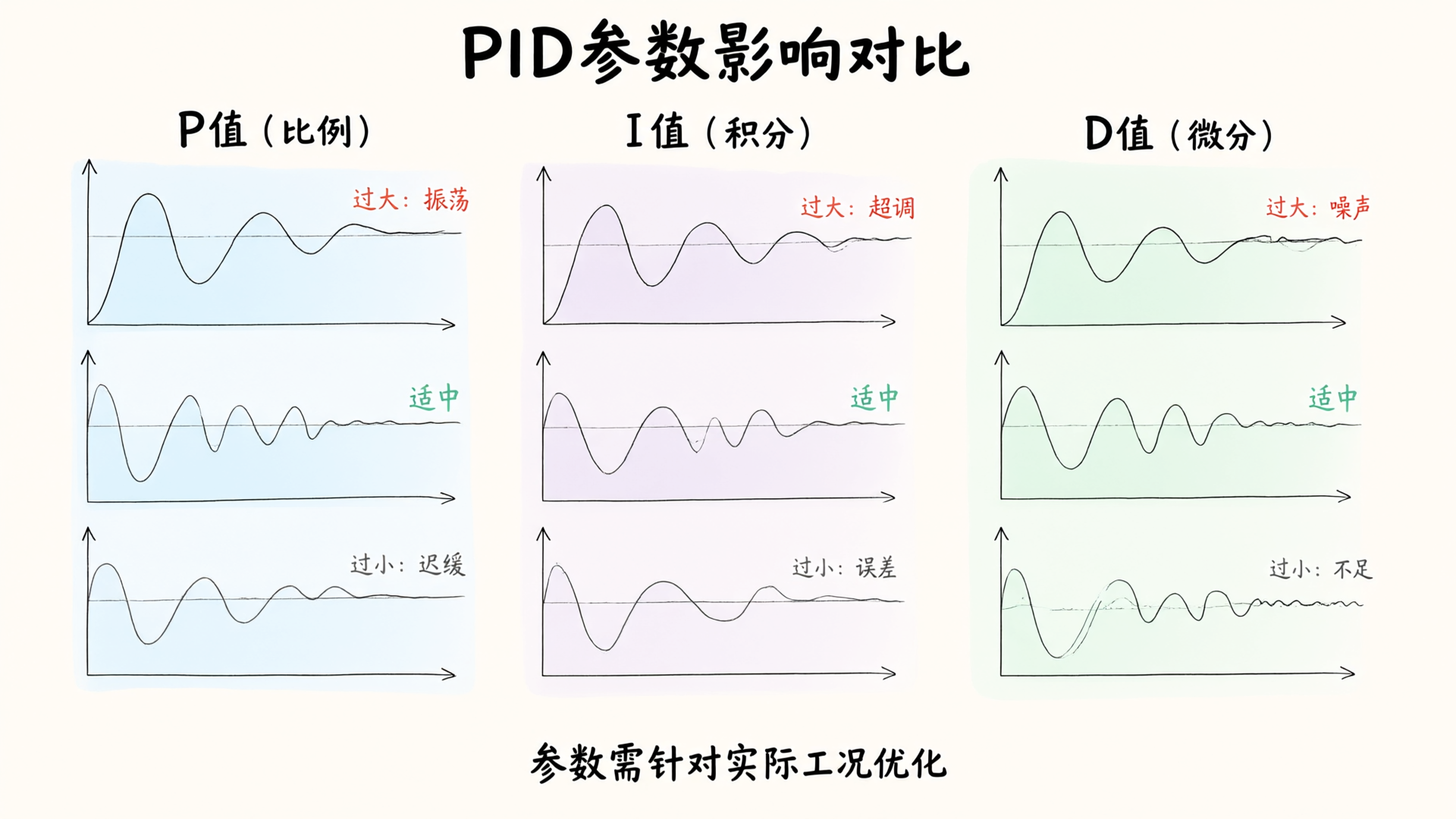
The proportional (P), integral (I), and derivative (D) parameters of a PID controller determine system response characteristics. An excessively high P value causes oscillation, while too low a P value results in sluggish response. A high I value leads to overshoot, whereas a low I value fails to eliminate steady-state error. A high D value is sensitive to noise, and a low D value provides limited suppression of overshoot.
Many users rely on factory-default controller settings or auto-tuning, but auto-tuning is not a universal solution. The algorithm assumes specific operating conditions; under rapidly changing loads or when heating power and thermal capacity are mismatched, auto-tuned results may deviate from optimal values. We found that approximately 40% of temperature fluctuation issues stem from PID parameters that were not optimized for actual operating conditions.
Solution: Perform auto-tuning under stable operating conditions and record the results as initial values. For load variation scenarios, manually fine-tune the P value (typically within ±10% to ±20%) while monitoring the response curve. For high-precision applications, use segmented PID control with different parameter sets for distinct temperature ranges.
Heater aging or power mismatch
The heater is an actuator; its performance degradation is a hidden cause of temperature fluctuations. Prolonged use causes the heating element wire to oxidize and deform, altering resistance and reducing heating power. Typical symptoms include extended warm-up times and failure to reach the target temperature at high settings.
Power mismatch issues are also common. During the design phase, heating power is calculated based on ideal conditions. In actual use, if the ambient temperature drops, ventilation improves, or the load increases, the original power may be insufficient. We once investigated a temperature issue in an oven for a plastic manufacturing company and found that when set to 200°C, the actual temperature reached only 185°C. The cause was that the original power design did not account for a 15°C drop in ambient temperature during winter.
Solution: Periodically measure the heater resistance and compare it to the initial value; replace if the deviation exceeds 10%. Design power with a 20% to 30% margin to accommodate operating condition changes. For multi-zone heating systems, adjust power independently per zone for easy post-deployment optimization.
Ambient temperature interference
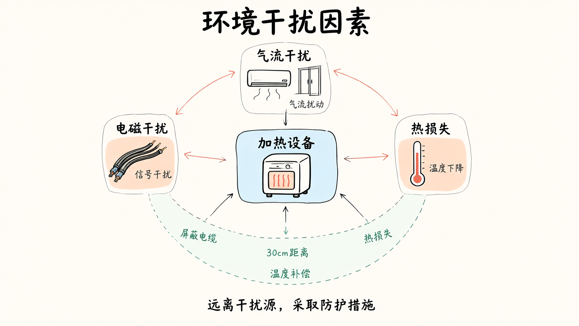
The temperature control system does not operate in isolation; ambient temperature fluctuations can compromise control accuracy through multiple pathways. Lower ambient temperatures increase heat loss, raising the heating load. Airflow disturbances affect thermocouple measurements, particularly in open or semi-open heating environments. Electromagnetic interference disrupts signal transmission, causing measurement value jumps.
A laboratory at an aerospace research institute experienced random temperature fluctuations of ±5°C with no discernible pattern. Investigation revealed that the air conditioner's outlet was blowing directly onto a drying oven, and the thermocouple signal cable was routed parallel to power cables. The issue was resolved by redirecting the airflow and replacing the signal cable with a shielded version.
Solution: Position heating equipment away from air vents, windows, and doors to avoid airflow interference. Use shielded cables for thermocouple signal lines, routing them separately from power cables with a minimum separation of 30 cm. For high-precision applications, consider adding ambient temperature compensation.
Control system response delay
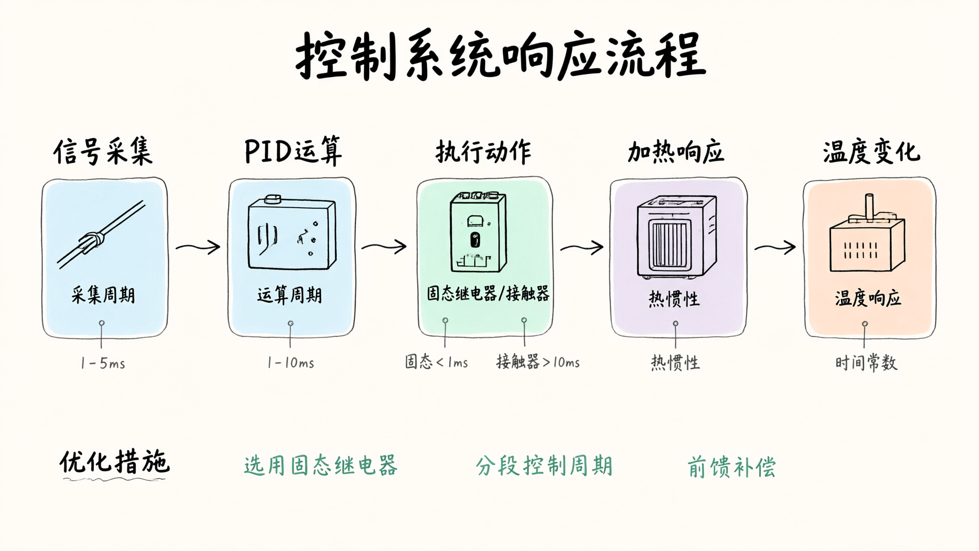
There is a time delay between receiving signals and outputting control actions. Sources of delay include: thermocouple signal acquisition cycle, PID computation cycle, solid-state relay or contactor actuation time, and heater thermal inertia. Excessive delay causes control actions to lag behind temperature changes, leading to oscillations.
Solid-state relays switch much faster than contactors, making them ideal for high-speed control applications. Heater thermal inertia depends on the material and structure: resistive wires have low inertia, while heating tubes exhibit high inertia. System design must account for delays across all stages to select an appropriate control cycle.
Solution: For fast-response applications, use a solid-state relay as the actuator. Set control cycles based on the principle: short cycle (1-3 seconds) for heating, long cycle (5-10 seconds) for holding temperature. For systems with high thermal inertia, implement feedforward control or Smith predictor compensation to correct delays proactively.
Systematic Troubleshooting Approach
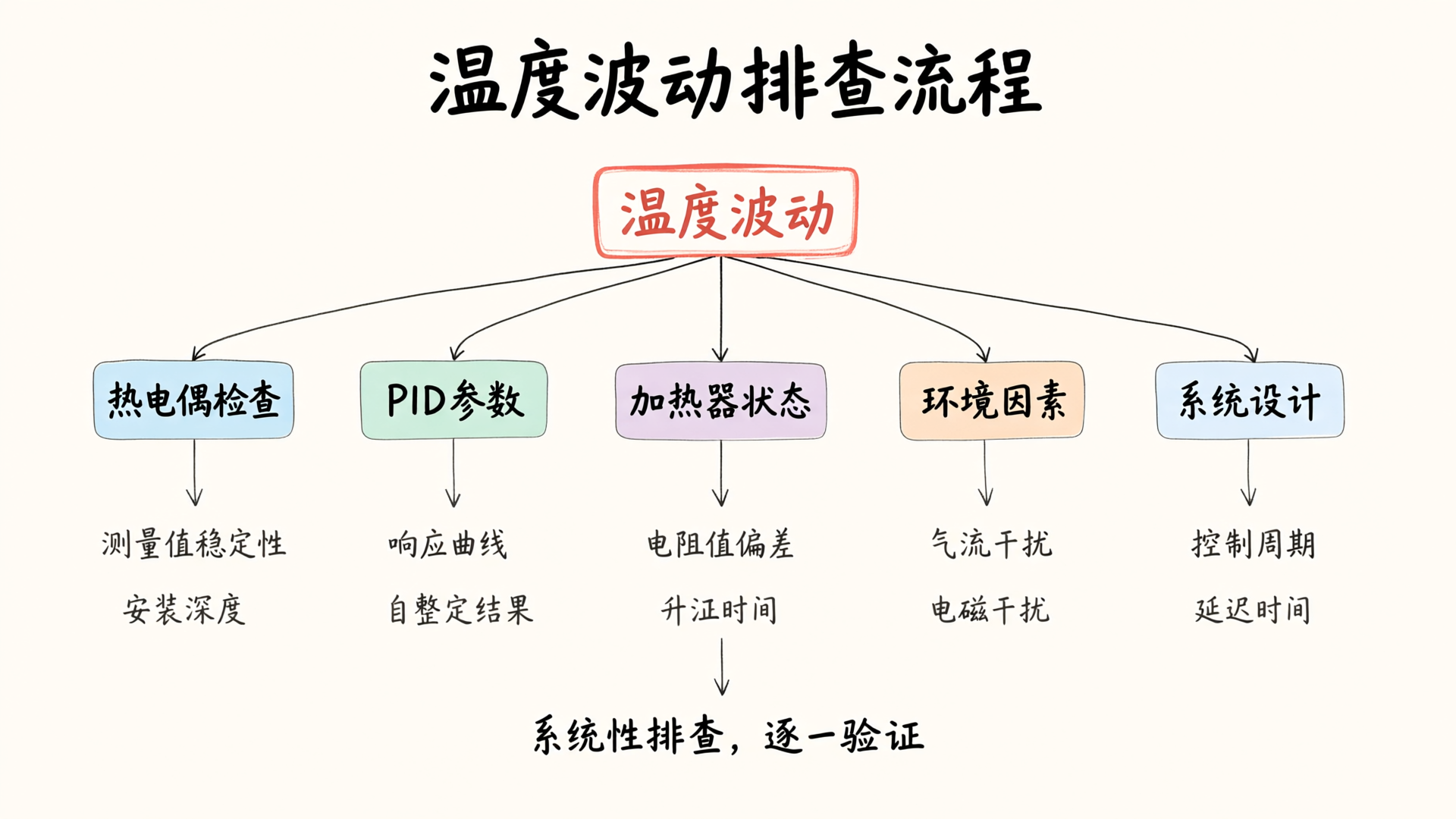
Temperature fluctuations often result from multiple contributing factors rather than a single cause. We recommend a systematic troubleshooting approach: first, verify that thermocouple readings are stable to rule out sensor issues; second, examine the PID output curve to assess parameter合理性; third, measure heater resistance to confirm actuator status; and finally, evaluate environmental conditions and system design.
We offer PID parameter optimization guidance and temperature control system diagnostics. If you encounter issues with temperature control, contact our technical team for tailored solutions.
Related Keywords
Frequently Asked Questions
What is the threshold for temperature fluctuation that indicates an anomaly?
In general industrial heating applications, a temperature deviation exceeding ±2% of the setpoint is considered abnormal. High-precision scenarios require deviations within ±0.5%.
Does auto-tuning always yield optimal PID parameters?
Not necessarily. Self-tuning relies on specific operating assumptions; if the load varies significantly or heating power does not match thermal capacity, results may deviate from optimal and require manual fine-tuning.
How do I know if the heater needs to be replaced?
Periodically measure the heater resistance. Replace it if the deviation from the initial value exceeds 10%. Additionally, significantly extended heating time or failure to reach the target temperature in the high-temperature stage are also typical signs of degradation.
Reference
- [1]IEC 60584 Thermocouple Standard
- [2]GB/T 15479 Industrial Automation Instruments Operating Conditions
Related Reading

A Conversation on Temperature Control Algorithms: From PID to Fuzzy PID, Exploring the Core Technologies of Omron, RKC, and Yamatake

How to Choose a PID Temperature Controller – 5 Parameters Help You Lock in a Solution in 3 Minutes

Optimizing Industrial Oven Temperature Uniformity: A Practical Guide to Airflow Design, Heating Element Layout, and Fan Selection
Need temperature control?
Our technical expert team will provide you with professional solutions and consulting services.
Get in Touch